1. A2 Ultra Overview
1. A2 Ultra Overview
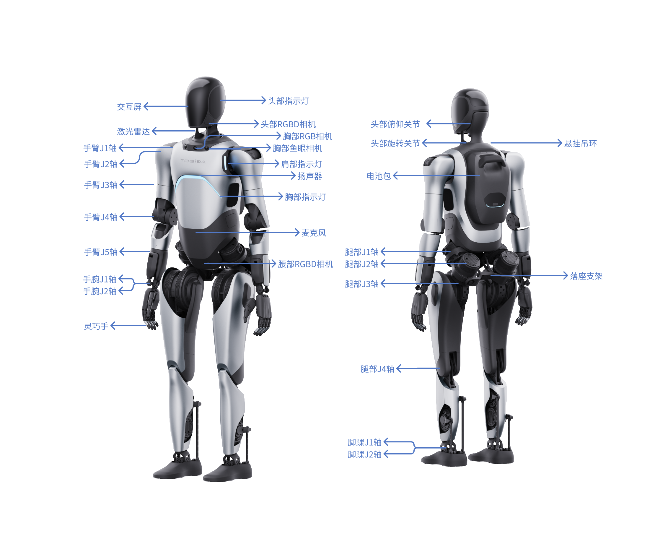
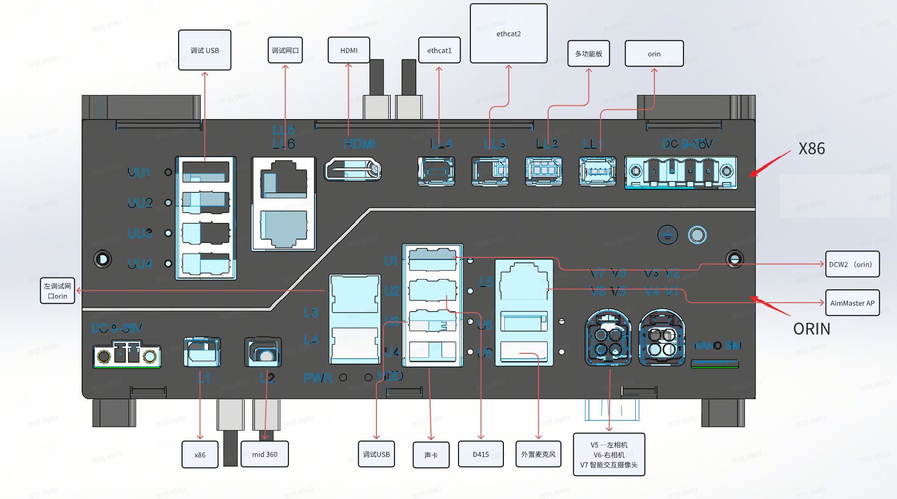
1.1 Component Description
1.2 Robot Specifications
| Primary Category | Secondary Category | Item | Specific Content |
|---|---|---|---|
| Product Basic Information | Height | 169cm | |
| Dimensions | 169(H)×75(W)×30(L)cm | ||
| Net Weight | ≈69kg | ||
| Product Features | Electrical Performance | Battery Life | Whole machine force control standing + voice broadcast: about 3 hours. Machine walking on flat ground with straight legs: about 1.5 hours. |
| Battery Capacity | 14.4Ah | ||
| Charging Time | 2h | ||
| Charging Power | ≤500W | ||
| Environmental Adaptability | Operating Temperature and Humidity | 0~ 40℃, relative humidity 10% ~ 90%, no condensation | |
| Storage Temperature and Humidity | -20℃~ 70℃, relative humidity 10% ~ 90%, no condensation | ||
| IP Rating | Joint Module: IP5X | ||
| Site Adaptability | Minimum Passage Width | Currently, the minimum width for remote control passage is >1m, and the minimum width for navigation passage is >2m | |
| Maximum Obstacle Height | 20mm | ||
| Safety | Arm Collision Sensing | Supported | |
| Maximum Obstacle Avoidance Detection Distance | 5m | ||
| Minimum Obstacle Avoidance Detection Height | 30cm | ||
| Operation and Interaction | Remote Control Operation | Wireless Remote Controller | |
| Interaction Screen | Facial interaction screen with emoticon display function Module overall dimensions: 105.50 × 67.20 × 3.0 mm (including frame) Actual display area: 95.04 × 53.86 mm Screen size: 4.3 inches Screen resolution: 800 × 480 pixels Brightness: 500 cd/m² Contrast: typical 1500:1, minimum 1000:1 | ||
| Speaker | Dual 5W | ||
| Indicator Light | Multi-color ambient light | ||
| Product Capabilities | Perception Capabilities | Environmental Perception | LiDAR: For collecting surrounding information, used for mapping and navigation. Parameters: Range: 0.2 - 40 m @ 10% reflectivity, 0.2 - 70 m @ 80% reflectivity, FOV: H: 360, V: -7~52, Ranging Error: 2 cm @ 10 m. RGBD Camera (Head) for target detection. Parameters: Depth map resolution: up to 1280x720, 640x480, Depth detection range: 0.3~ 10 m, FOV: HFOV: 65° ± 2°, VFOV: 40° ± 1°. RGB Camera (Chest) for target detection. Parameters: FOV: H196V154, Resolution: 1920Hx1536V. RGBD Camera (Groin) for target detection. Parameters: Depth map resolution: 640 x 400@5/10/15fps, Depth detection range: Normal mode 0.15-3m, High mode 0.15-5m, FOV: HFOV: RGB FOV: 16:9: H86° V55°. Fisheye Camera (Left/Right Chest) for forward perception. Parameters: FOV: H196V154, Resolution: 1920Hx1536V |
| Navigation Capabilities | Positioning Accuracy | ±10cm, ±10° | |
| Navigation and Obstacle Avoidance | Supports real-time autonomous navigation and obstacle avoidance | ||
| Movement Modes | Supports forward, left turn, right turn | ||
| IoT Capabilities | Communication Protocols | TCP, IP | |
| Communication Modules | WiFi, Cellular Network | ||
| Arm Typical Parameters | Dexterous Hand Delivery Capability | Grasping weight (palm down): <3kg Hook grip weight (palm up): <8kg | |
| Maximum Load for Arm (with Dexterous Hand) | 2kg | ||
| Arm Workspace | J1(Shoulder pitch): ±170° | ||
| J2(Shoulder roll): -30°~95° | |||
| J3(Shoulder yaw): ±170° | |||
| J4(Elbow pitch): -1°~118° | |||
| J6(Wrist pitch): ±45° | |||
| J7(Wrist yaw): ±30° | |||
| Typical Leg Parameters | Leg workspace (with some deviation) | J1(Hip roll): -37~40° | |
| J2(Hip yaw): ±75° | |||
| J4(Knee pitch): -5°~140° | |||
| J5(Ankle pitch): -30°~52° | |||
| J6(Ankle roll): ±28° | |||
| Typical Head Parameters | Head Movement Range | Pitch joint: ±23° |
1.3 Industrial PC Specifications
The A2 Ultra robot is pre-installed with two upper-level development boards, which communicate directly via Ethernet. One of the boards is for the cerebellum control and is not allowed to be modified; the other is the brain development board, using Nvidia Jetson AGX Orin 64 GB. The specifications can be found in the Nvidia official documentation.
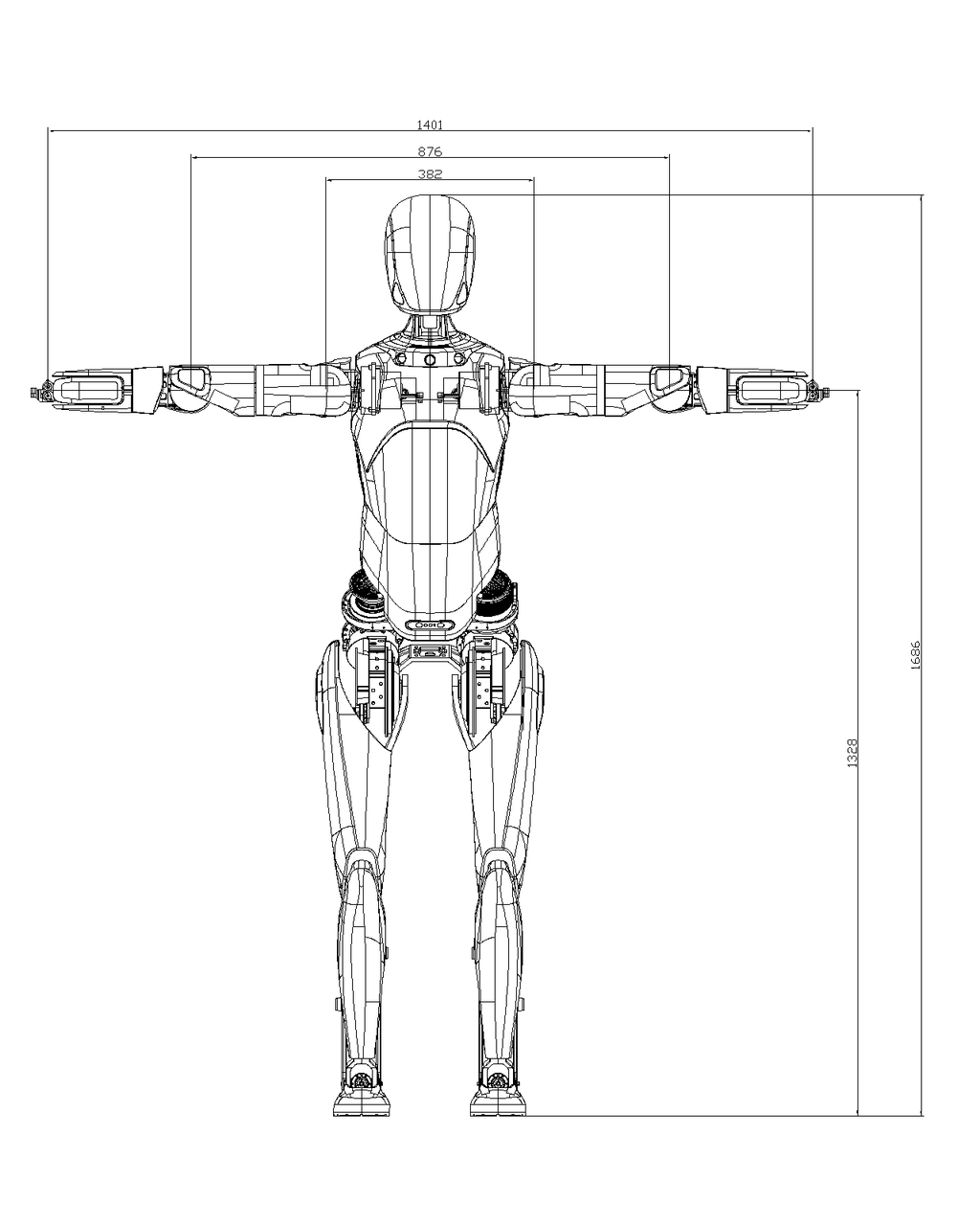
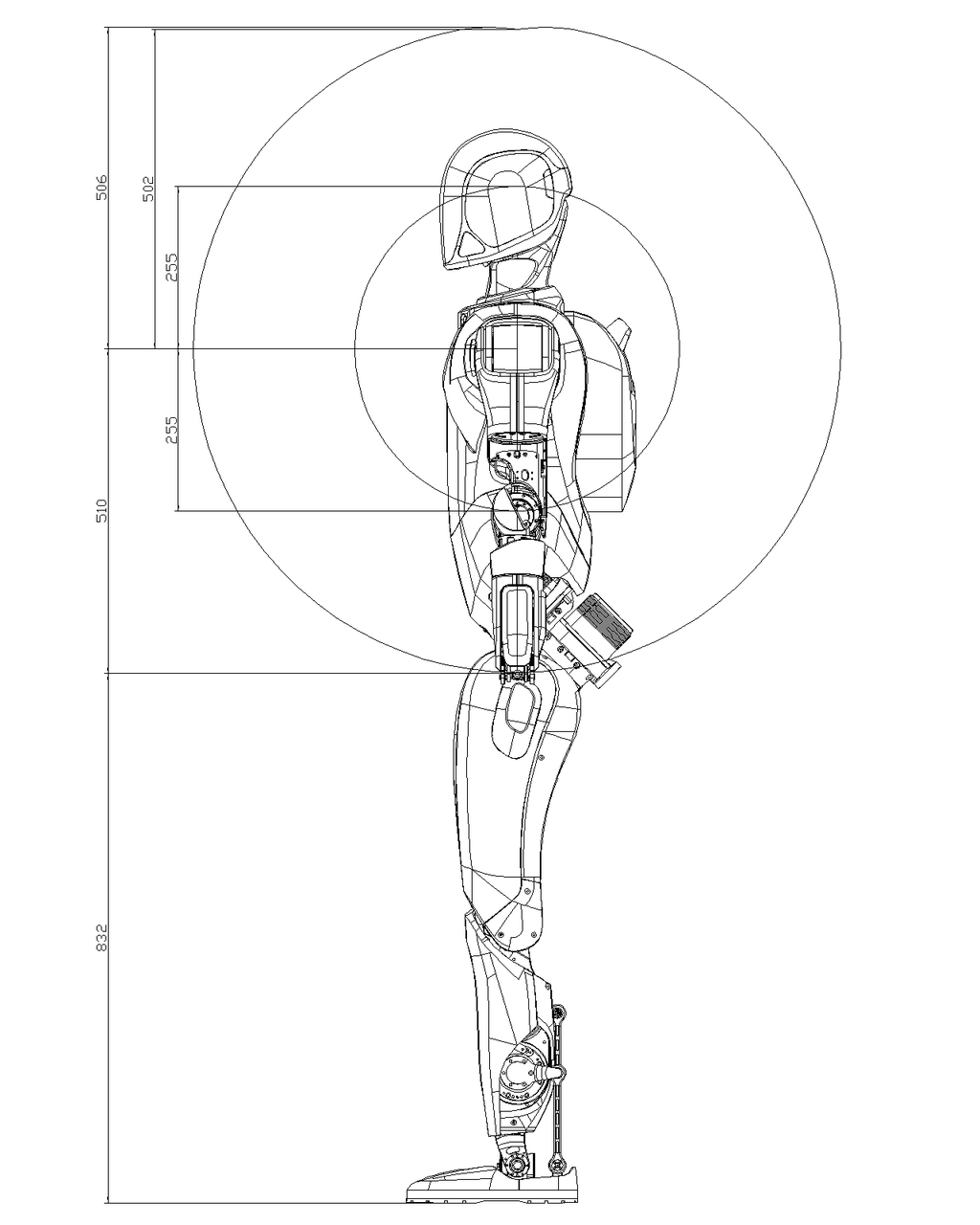
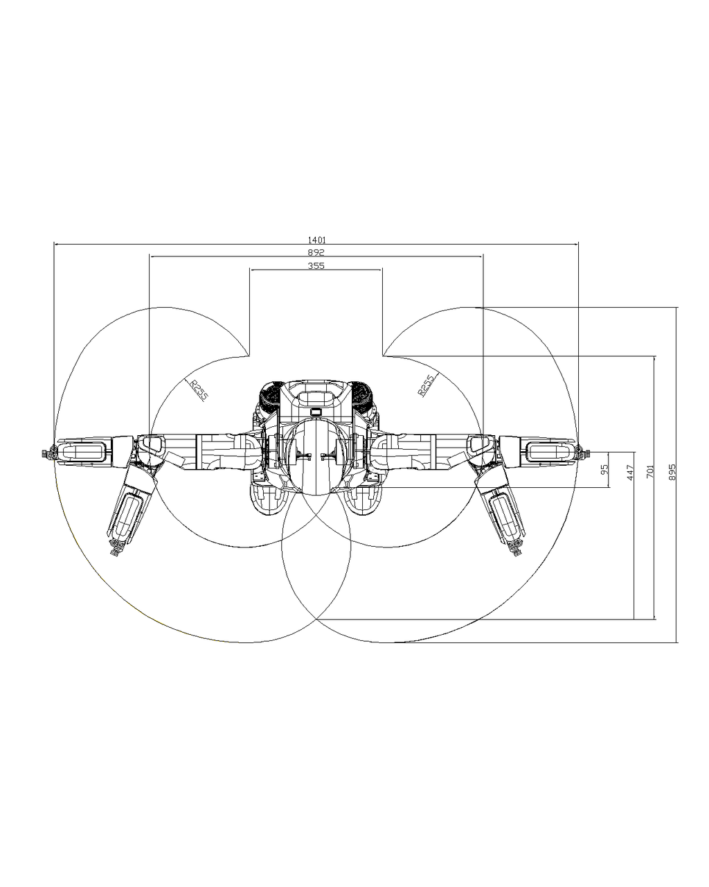
1.4 Whole Machine Workspace
Calculated from the center point of the wrist joint
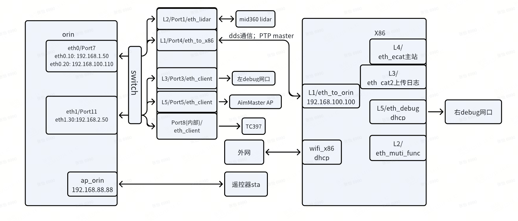
1.5 Network Topology
The A2 robot has two different hardware models, with different suppliers and hardware designs, resulting in different network topologies. These are referred to as the T3 model and the P1 model.
You can determine the model by checking the network interface names using the ip a command on the actual machine.
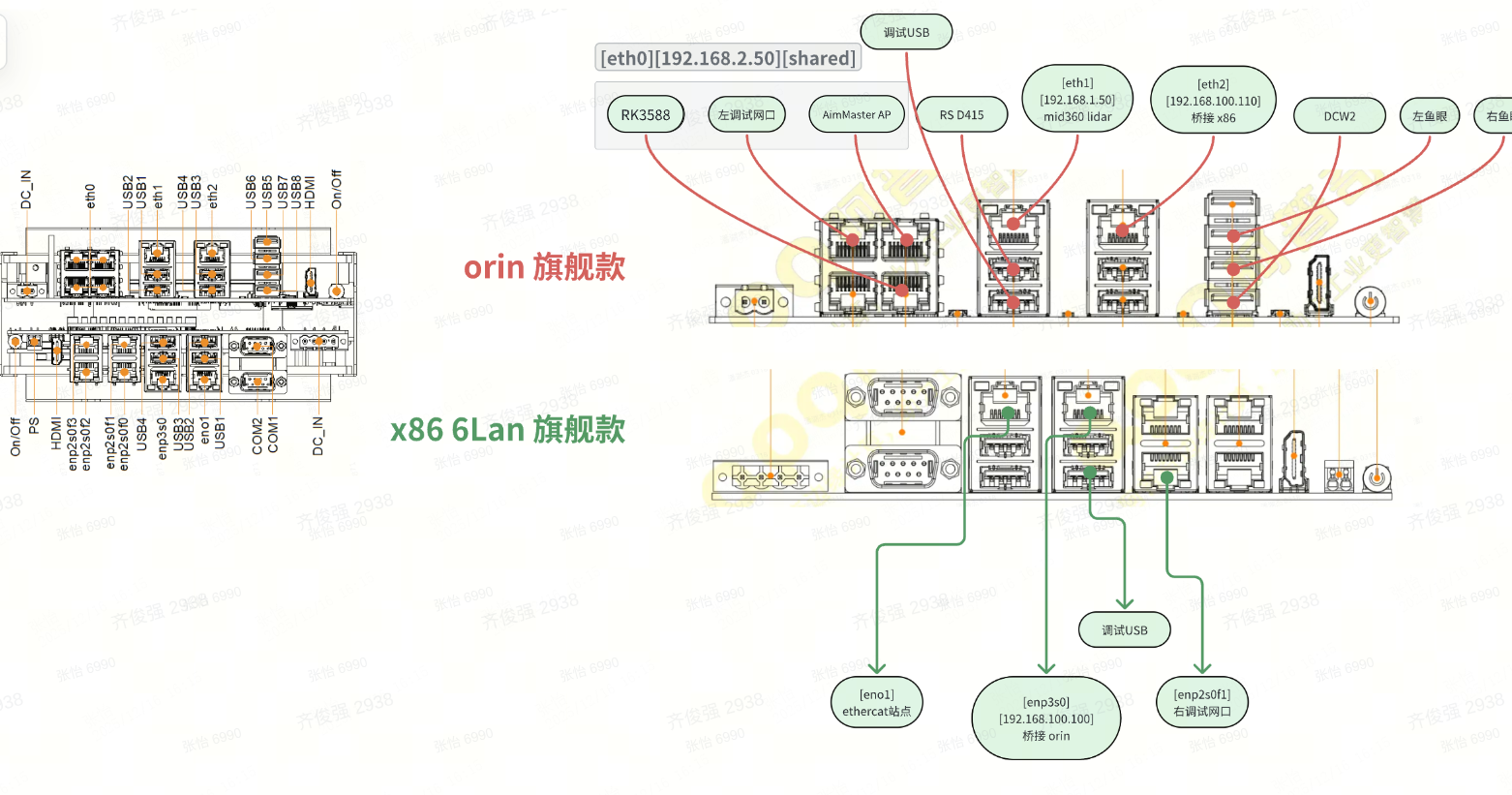
1.5.1 T3 Model
Hardware architecture diagram
Software network topology diagram
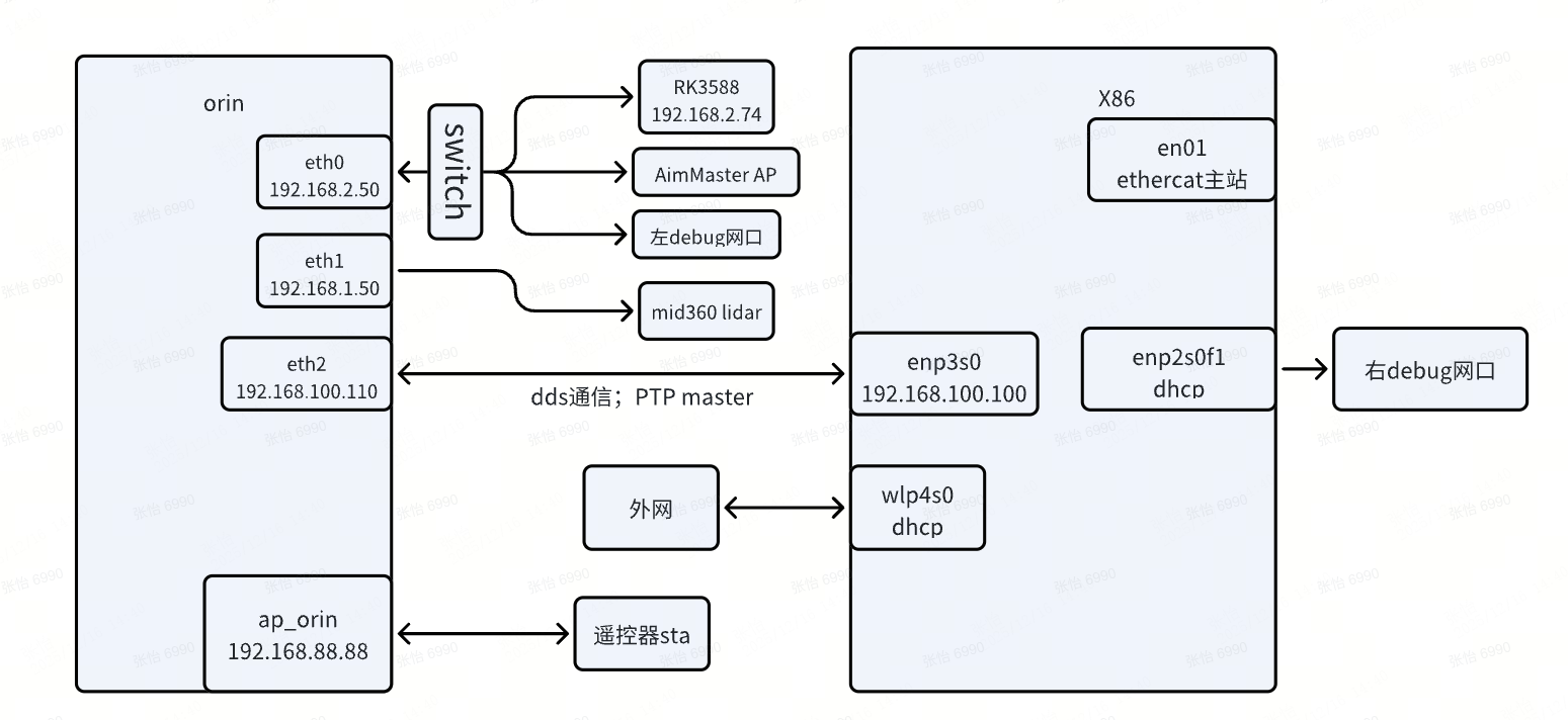
Where:
- The left debug network port is for the orin debugging, with a fixed IP of 192.168.2.50. The right debug network port is for x86 debugging, using DHCP mode.
1.5.2 P1 Model
Hardware architecture diagram
Software network topology diagram
Where:
- The left debug network port is for the orin debugging, with a fixed IP of 192.168.2.50. The right debug network port is for x86 debugging, using DHCP mode.
1.5.3 Network NAT Configuration
Starting from software version V1.2, due to hardware and software architecture reasons, the default network policy of the robot has been adjusted to disable the ORIN's own WiFi and instead use the x86 WiFi for NAT internet access. The policy details are as follows:
- When the X86 WiFi is enabled, the ORIN module's internet traffic defaults to flow through the 192.168.100.1 gateway to the X86 for NAT internet access.
- When the X86 WiFi is disabled, the ORIN's external internet traffic defaults to flow through the 5G module. If the 5G module does not have a SIM card or no network, it will not be able to connect to the internet.
This network policy brings up an issue where users cannot directly access services on the ORIN. To address this, we provide two solutions:
- You can connect to the ORIN's AP hotspot. The default password can be found in the
password.mdfile in the AimDK package. This allows direct access to the ORIN hotspot IP. - You can configure port forwarding on the X86, accessing the corresponding port on the X86 to forward to the ORIN's corresponding port. The configuration file is located at
/opt/orin_use_x86_wifi/x86_cfg.shon the X86. An example of the forwarding entry is as follows (the network interface names may differ for different models, but the principle is similar):bashsudo iptables -t nat -A PREROUTING -i wifi_x86 -p tcp --dport 51056 -j DNAT --to-destination 192.168.100.110:51056 sudo iptables -t nat -A POSTROUTING -d 192.168.100.110 -p tcp --dport 51056 -j SNAT --to-source 192.168.100.100
New forwarding entries can be added to modify the forwarding and destination ports to support more port forwarding.
1.6 Camera Views
The A2 Pro is equipped with RGB-D cameras on the head and waist, and a fisheye camera on the chest. For exact locations, please refer to the component descriptions in the Overview section of this document.
- FOV DiagramsSide
Side view diagram of the head/waist RGB-D camera FOV: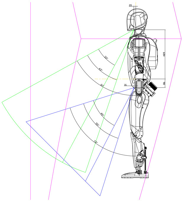
Front view diagram of the head/waist RGB-D camera FOV: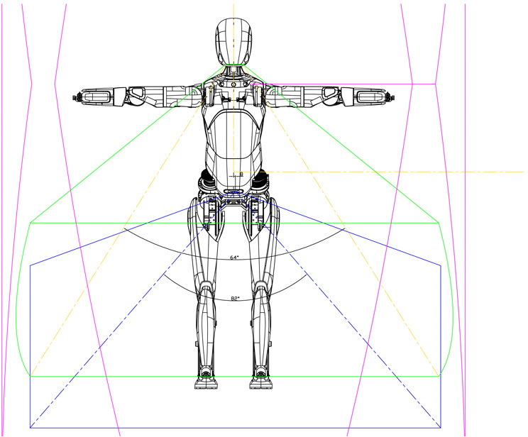
Top-down view diagram of the head/waist RGB-D camera and chest fisheye camera FOV: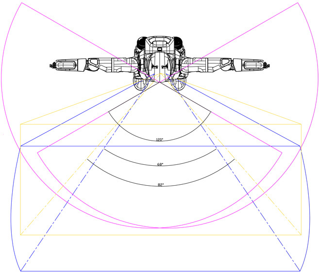
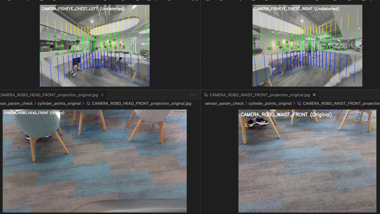
- Diagram of the Fisheye Camera's FOV after Distortion Correction
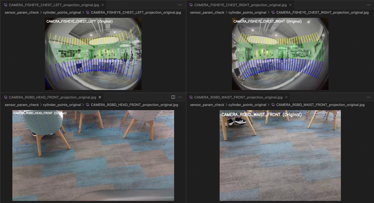
Diagram of the Fisheye Camera's FOV before Distortion Correction: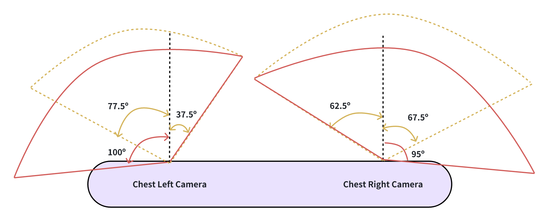
Diagram of the fisheye camera's FOV after distortion correction. The field of view represented in this diagram is used for the fisheye camera in practical applications.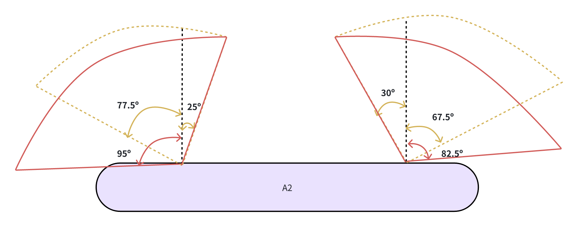
The distortion correction was performed using scatter points at a distance of 2m from the Baselink, with a vertical resolution of 5cm per point and a horizontal angular resolution of 5 degrees. The comparison of the effect before and after distortion correction is shown in the figure below:Before Distortion Correction After Distortion Correction