
7.4 Sensor Data Section
7.4 Sensor Data Section
7.4.1 Overview
The A2 Ultra model is equipped with a variety of sensors, including cameras, radars, and IMUs. The specific positions of the sensors can be found in the component descriptions in the overview section of this document.
We provide ROS2 topic interfaces for the raw frame data of each sensor, all using standard ROS2 messages. Instead of listing each individual interface, we provide a unified table of topics, along with intrinsic and extrinsic parameter files and usage instructions.
7.4.2 Sensor Topic Interface
Some cameras have different model specifications on different models, and the differences are listed in the table by model.
Camera topic subscription example can be found at examples/sensors/camera.py
Radar topic subscription example can be found at examples/sensors/lidar.py
IMU topic subscription example can be found at examples/sensors/imu.py
Raw frame interface:
| Topic Name | Message Type | Sensor Model | Data Stream | Resolution | Frame Rate |
|---|---|---|---|---|---|
| /aima/hal/fish_eye_camera/chest_left/color | sensor_msgs::msg::Image | Chest left fisheye camera Senyun ISX031C-H190XA (P1) Xinying OG02B10 (T3) | Color image (color) | 640x480 | 30 Hz |
| /aima/hal/fish_eye_camera/chest_right/color | sensor_msgs::msg::Image | Chest right fisheye camera Senyun ISX031C-H190XA (P1) Xinying OG02B10 (T3) | Color image (color) | 640x480 | 30 Hz |
| /aima/hal/rgbd_camera/head_front/color | sensor_msgs::msg::Image | Head RGB-D camera Realsense D415 | Color image (color) | 1280x720 | 15 Hz |
| /aima/hal/rgbd_camera/head_front/depth | sensor_msgs::msg::Image | Head RGB-D camera Realsense D415 | Depth image (depth) | 1280x720 | 15 Hz |
| /aima/hal/rgbd_camera/waist_front/color | sensor_msgs::msg::Image | Waist RGB-D camera Orbbec DCW2 | Color image (color) | 640x480 | 10 Hz |
| /aima/hal/rgbd_camera/waist_front/depth | sensor_msgs::msg::Image | Waist RGB-D camera Orbbec DCW2 | Depth image (depth) | 640x480 | 10 Hz |
| /aima/hal/lidar/neck/pointcloud | sensor_msgs::msg::PointCloud2 | Neck LiDAR Mid360 | Point cloud data (pcd_option) | - | 10 Hz |
| /aima/hal/lidar/neck/imu | sensor_msgs::msg::Imu | Neck LiDAR Mid360 | IMU data (imu_option) | - | 200 Hz |
| /body_drive/imu/data | sensor_msgs::msg::Imu | Waist IMU YISENSE YI 320 | IMU data (imu_option) | - | 1000Hz |
On the P1 model, /aima/hal/camera/interactive/color is published by default using the iceoryx backend, which can be cumbersome to call. The following method is provided to modify its publishing backend to add a ROS2 backend (the 1.2/1.0 versions still retain compatibility with the iceoryx method, but it is recommended to modify and subscribe via the standard ROS2 interface in the new version). Note that after adding the ROS2 backend, the tz_camera module will have a 14% increase in CPU usage.
Method to add ROS2 backend on P1 model:
- First, back up the corresponding configuration file on ORIN
bashcp /agibot/software/v0/config/tzcamera/tzcamera_config.yaml /agibot/software/v0/config/tzcamera.tzcamera_config.yaml.original- Then, modify the file to add ros2 to the enable_backends of /aima/hal/camera/interactive/color in aimrt.channel.pub_topic_options, changing from iceoryx to iceoryx, ros2
- Restart the robot
Under normal operation of the robot, all sensor topics should continuously publish data after initialization, with the following exception:
- On the T3 model, /aima/hal/camera/interactive/color has no data in interactive silent mode.
For color images, an h264 encoding interface is provided (experimental interface, no example call script provided yet, familiarity with h264 and other image encoding knowledge is required):
| Topic Name | Message Type | Sensor Model | Data Stream | Resolution | Frame Rate |
|---|---|---|---|---|---|
| /aima/hal/fish_eye_camera/chest_left/color/h264 | foxglove_msgs::msg::CompressedVideo | Chest left fisheye camera Senyun ISX031C-H190XA (P1) Xinying OG02B10 (T3) | Color image (color) h264 encoded | 640x480 | 5 Hz, I-frame interval 5, one keyframe per second |
| /aima/hal/fish_eye_camera/chest_right/color/h264 | foxglove_msgs::msg::CompressedVideo | Chest right fisheye camera Senyun ISX031C-H190XA (P1) Xinying OG02B10 (T3) | Color image (color)h264 encoded | 640x480 | 5 Hz, I-frame interval 5, one keyframe per second |
| /aima/hal/rgbd_camera/head_front/color/h264 | foxglove_msgs::msg::CompressedVideo | Head RGB-D camera Realsense D415 | Color image (color)h264 encoded | 1280x720 | 5 Hz, I-frame interval 5, one keyframe per second |
| /aima/hal/rgbd_camera/waist_front/color/h264 | foxglove_msgs::msg::CompressedVideo | Waist RGB-D camera Orbbec DCW2 | Color image (color)h264 encoded | 640x480 | 5 Hz, I-frame interval 5, one keyframe per second |
| /aima/hal/camera/interactive/color/h264 | foxglove_msgs::msg::CompressedVideo | Chest middle interactive camera Senyun ISX031C-H100F1A (P1) Xunfei multimodal interactive camera (T3) | Color image (color)h264 encoded | 1920x1536 (P1) No such topic for T3 | 5 Hz, I-frame interval 5, one keyframe per second |
7.4.3 Calibration Parameter Description
The A2 Ultra model is equipped with a variety of sensors such as cameras, radars, and IMUs. The specific positions of the sensors can be found in the component description in the overview section of this document.
We provide ROS2 topic interfaces for the raw frame data of each sensor, all using standard ROS2 messages. Instead of listing each individual interface, we provide a unified topic description table along with the intrinsic and extrinsic parameter files and usage instructions.
Aligning depth and color images from a pinhole camera example can be found in examples/sensors/rgbd_align.py
Undistorting fisheye camera images example can be found in examples/sensors/fisheye_undistorted.py
The directory where the calibration results for the camera's intrinsic and extrinsic parameters are saved (located on ORIN):
/agibot/data/param/calibration/
The folder contains the following files:
- Extrinsic Parameters:
- extrinsic_baselink_T_chest_left.txt: Represents the extrinsic parameters from base_link to the left fisheye camera (x, y, z, qw, qx, qy, qz)
- extrinsic_chest_right_T_chest_left.txt: Represents the extrinsic parameters from the left camera to the right camera (x, y, z, qw, qx, qy, qz)
- extrinsic_baselink_T_head_front.txt: Represents the extrinsic parameters from base_link to the front head camera (x, y, z, qw, qx, qy, qz)
- estrinsic_waist_front_T_baselink.txt: Represents the extrinsic parameters from base_link to the front waist camera (x, y, z, qw, qx, qy, qz)
- estrinsic_baselink_T_lidar.txt: Represents the extrinsic parameters from the lidar to base_link (x, y, z, qw, qx, qy, qz)
- gravity_T_imu.txt: Represents the rotation from the IMU to base_link (qw, qx, qy, qz)
- Intrinsic Parameters:
- intrinsic_chest_left.yaml: Intrinsic parameters for the left fisheye camera
- intrinsic_chest_right.yaml: Intrinsic parameters for the right fisheye camera
- intrinsic_head_front.yaml: Intrinsic parameters for the front head camera
- intrinsic_wasit_front.yaml: Intrinsic parameters for the front waist camera
Note:
- x, y, z denote the translation; qw, qx, qy, qz represent the quaternion (Hamilton convention) for rotation.
- The data in the extrinsic file describes a coordinate transformation. For instance, the extrinsic parameters in extrinsic_baselink_T_head_front.txt indicate the position and orientation of the base_link frame relative to the head camera frame.
7.4.3.1 Reading Pinhole Camera Intrinsic Parameters
Example of pinhole camera intrinsic parameters (intrinsic_head_front.yaml):
%YAML:1.0
---
model_type: PINHOLE
camera_name: ""
image_width: 1280
image_height: 720
distortion_parameters:
  k1: 8.4721332081814996e-02
  k2: -2.2328724059363472e-01
  p1: 1.4980714426687237e-02
  p2: 5.8573350999184884e-03
projection_parameters:
  fx: 9.4067882179688206e+02
  fy: 9.3408163057525098e+02
  cx: 6.3075913699847933e+02
  cy: 3.7669033617329160e+02
fx, fy, cx, cy correspond to the camera intrinsic matrix, k1, k2, p1, p2 correspond to distortion coefficients.
An example of the corresponding reading function is as follows:
// Pinhole camera intrinsic reading function
bool ReadFromYamlFile(const std::string& filename)
{
    cv::FileStorage fs(filename, cv::FileStorage::READ);

    if (!fs.isOpened())
    {
        return false;
    }

    if (!fs["model_type"].isNone())
    {
        std::string sModelType;
        fs["model_type"] >> sModelType;

        if (sModelType.compare("PINHOLE") != 0)
        {
            return false;
        }
    }

    std::string model_type_ = "PINHOLE";
    std::string camera_name_;
    fs["camera_name"] >> camera_name_;
    int image_width_  = static_cast<int>(fs["image_width"]);
    int image_height_ = static_cast<int>(fs["image_height"]);

    cv::FileNode n = fs["distortion_parameters"];
    double k1_            = static_cast<double>(n["k1"]);
    double k2_            = static_cast<double>(n["k2"]);
    double p1_            = static_cast<double>(n["p1"]);
    double p2_            = static_cast<double>(n["p2"]);

    n   = fs["projection_parameters"];
    double fx_ = static_cast<double>(n["fx"]);
    double fy_ = static_cast<double>(n["fy"]);
    double cx_ = static_cast<double>(n["cx"]);
    double cy_ = static_cast<double>(n["cy"]);

    return true;
}
7.4.3.2 Reading Fisheye Camera Intrinsic Parameters
Example of fisheye camera intrinsic parameters (intrinsic_chest_left.yaml):
%YAML:1.0
---
model_type: KANNALA_BRANDT
camera_name: ""
image_width: 640
image_height: 480
projection_parameters:
  k2: 4.0154631284881101e-02
  k3: -1.9502762632935614e-02
  k4: 8.9682432239682577e-04
  k5: -5.0758203706675745e-04
  mu: 1.9728857021424918e+02
  mv: 1.9697037865238804e+02
  u0: 3.1897257040247649e+02
  v0: 2.4312745081143589e+02
u0, v0, mu, mv correspond to the camera intrinsic matrix, k2, k3, k4, k5 correspond to distortion coefficients.
An example of the corresponding reading function is as follows:
// Fisheye camera intrinsic reading function
bool ReadFromYamlFile(const std::string& filename)
{
    cv::FileStorage fs(filename, cv::FileStorage::READ);

    if (!fs.isOpened())
    {
        return false;
    }

    if (!fs["model_type"].isNone())
    {
        std::string sModelType;
        fs["model_type"] >> sModelType;

        if (sModelType.compare("KANNALA_BRANDT") != 0)
        {
            return false;
        }
    }

    std::string model_type_ = "KANNALA_BRANDT";
    std::string camera_name_;
    fs["camera_name"] >> camera_name_;
``````cpp
    int image_width_  = static_cast<int>(fs["image_width"]);
    int image_height_ = static_cast<int>(fs["image_height"]);

    cv::FileNode n = fs["projection_parameters"];
    double k2_            = static_cast<double>(n["k2"]);
    double k3_            = static_cast<double>(n["k3"]);
    double k4_            = static_cast<double>(n["k4"]);
    double k5_            = static_cast<double>(n["k5"]);
    double mu_            = static_cast<double>(n["mu"]);
    double mv_            = static_cast<double>(n["mv"]);
    double u0_            = static_cast<double>(n["u0"]);
    double v0_            = static_cast<double>(n["v0"]);

    return true;
}
7.4.3.3 Camera extrinsics loading
Data format corresponding to camera extrinsics:
x, y, z, qw, qx, qy, qz
The reading function is as follows:
// Extrinsic parameter reading function
bool ReadPoseFromFile(const std::string& file_name, SE3d& pose)
{
    if (!std::filesystem::exists(file_name))
    {
        LOG(WARNING) << "pose file don't exists!" << file_name;
        return false;
    }

    std::ifstream     pose_ifs(file_name);
    Eigen::Quaternion rot   = pose.unit_quaternion();
    Vec3d             trans = pose.translation();
    pose_ifs >> trans.x() >> trans.y() >> trans.z() >> rot.w() >> rot.x() >> rot.y() >> rot.z();
    pose = SE3d(rot, trans);
    pose_ifs.close();
    return true;
}
7.4.4 P1 model camera device released
Notice:Releasing the camera device is a high-risk operation and is generally not recommended. After releasing the camera, the Zhiyuan interaction will be affected regardless of whether it exits the Zhiyuan interaction link, resulting in no camera data. This operation should only be performed when the system's ROS2 interface cannot meet development needs and the user has the underlying requirements and development capabilities for camera development.
The A2 flagship P1 model features three cameras on its chest (left and right fisheye cameras and a central interactive camera), which are occupied by system processes by default. Users can release and take over control of the cameras using the following steps (the T3 model does not currently have this camera release function). The following example demonstrates the specific process of releasing the central interactive camera.
- Modify the file /agibot/software/v0/config/tzcamera/tzcamera_config.yaml in the orin directory, and delete the configuration entries for the cameras that need to be accessed separately (in this case, the intermediate interactive camera).
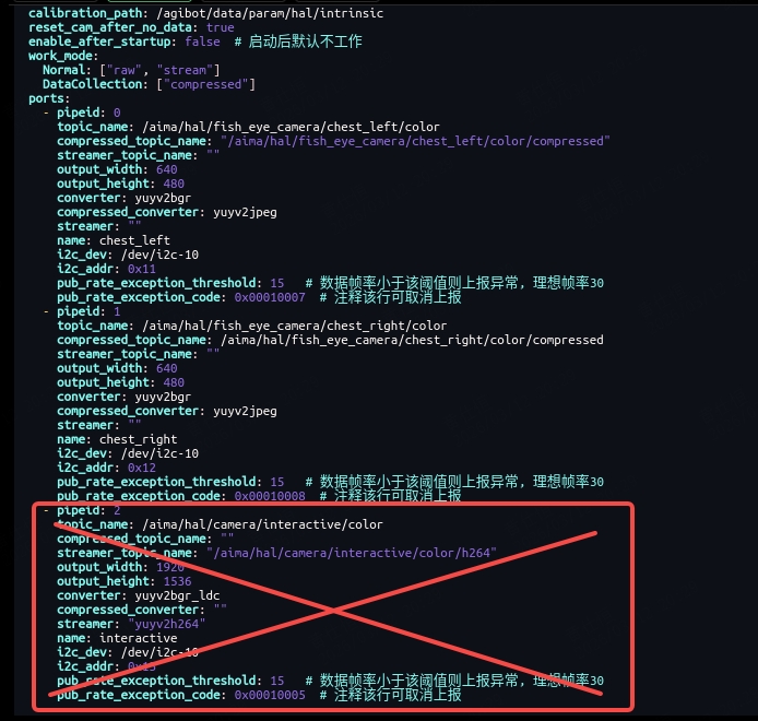
- Make the changes take effect:
Choose any of the following methods to apply the configuration changes:
- Method 1: Restart the tz_camera modulebash
aima em stop-app tz_camera //Stop the tz_camera module aima em start-app tz_camera //Restart the tz_camera module - Method 2: Restart the robot
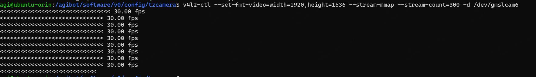
- Verify that the camera has been released:
Execute the following command in the ORIN terminal to test whether the intermediate interactive camera (/dev/gmslcam6) can be accessed independently:
v4l2-ctl --set-fmt-video=width=1920,height=1536 --stream-mmap --stream-count=300 -d /dev/gmslcam6
If the command runs normally, it indicates that the camera has been successfully released.
- Device name:
The device nodes corresponding to each camera are as follows:
- Left fisheye camera:
/dev/gmslcam4 - Right side fisheye camera:
/dev/gmslcam5 - Interactive camera in the middle:
/dev/gmslcam6
- References
The P1 model uses the G3-ISX031C-GMSL2F-H100F1 camera for the center chest and the Sensing SG3-ISX031C-GMSL2F-H190X camera for the left and right fisheye lenses. Development materials are available on the Sensing website: https://www.sensing-world.com/h-pd-307.html